If I have written a tip in this font, I have personally verified it. If it is written like this, I found it on the Internet and am awaiting verification. These are the ones to take with a grain of salt. If you want machine specific tips not related to CNC (i.e. applicable to CNC or manual machining), there are several pages for the lathe and mill.
If you want to plunge in, here is a rough play by play for how it should go in 3 axes. When you draw your part in your cad system, you should place one corner of it so that the top of that corner is at X0Y0Z0. This is the datum, or reference point for that part, and is called Work Zero. When you power up your machine and it homes, all the axis are in certain positions which the machine calls home, and typically these would all be zero, or they might be assigned particular values. This location is called Machine Zero, or just the Home Position. Often the home position will be the position where the machine can access the toolchanger if there is one, or perhaps it will be the maximum positive values for all axes. A switch is often located there so the machine can positively find it again. Clamp your stock down on the table. You want to reconcile the origin of the stock relative to the machine zero. So, pick a corner of your stock and say, "This is my datum point or Work Zero". This should correspond with the position of your stock in the cad screen. Through a series of jog movements, and use of an edge finder (precise method) or a sharp point held in the spindle (crude method) you move the spindle to where the Work Zero datum on the stock lies. At this time, the machine's axis displays show your jog amounts from machine zero, so these X and Y values are entered into your G54 work offset. These values represent how far the datum on the part is from the machine zero. There is no need to enter a Z G54 work offset at this time, because the tools have not been loaded as you are just working with an edge finder or point probe. Now, load the tool and jog in Z from machine home down to the top of the part. Whatever this distance is, you could use for your tool length offset for that tool (see below for more info on tool length offsets!). All the tools could be measured in this manner. Thus, because the tool length offset sets all the tools to the same Z level, you are done, there is nothing to set in the Z G54 work offset, which should be zero. Your program needs a T1 M6 command to load a tool from the toolchanger and an G43 H1 command to load the length offset for that tool. It is simplist if you use H1 with T1, H2 with T2. Even if you do not have a toolchanger, the T number in your program is really only for your reference, because the H number will execute the length offset. Now if it bugs you to set (and reset) all the tools to the top of the work, then you can set the tools to the table, or to a reference block that is sitting on the table. In such an instance, then you set all your tool length offsets to that reference, each and every time. This is the preferred method. But, this introduces one more step, and you do make use of the G54 Z work offset for this. After any of your tool length offsets are set to the reference, you then need to measure the height from the reference to the top of the stock. If you zero the display temporarily when the tool is touching the top of the reference, then you can jog up or down as required to touch the top of the stock. This will give you a direct measurement which will be inserted in the G54 Z register. Near the very start of your program, you need to call for the machine to use the G54 work offset. Just insert G54 into your program. For trial, after you call G54, then call G00 X0 Y0 and the table should move to position the tool over the corner reference of the part. Note, in some systems, like Mach 3, G54 is the default, and you need not call G54 explicitly. Then G43 H1 G00 Z1. should position the tool 1" above the corner of the part. If you are cautious, turn your rapid override down real slow, and watch the motion happen. Or you could use G01 in place of G00 and use a slow feedrate to make sure stuff is happening as you expect. Be ready to hit the feedhold or E stop if you see a collision coming You can return the machine to home with a G53 X0 Y0 Z0 command, if Z0 is the homed position of the Z axis. G53 is the name of the machine coordinate system. Some say that it "cancels the work offset" but really, you are just dropping back into the 'real' coordinate system that the machine works in. The work offsets are just an imaginary shift of the coordinate system zero for convenience sake.
Total Height = fixture height + work height + tool height
What about shortcuts? Well, you could dispense with the edgefinder to find the X, Y work offsets and just job to a suitable point that's "close" by eyeball but within the material and cut the machine loose. This assumes you can do all of the machining in one setup. If, for some reason, you need multiple setups, then you have to be able to precisely locate the Work Zero setup on subsequent setups or the machine won't be aligned properly and nothing will come out right. It is also possible that you have a fixture that enables you to swap to the next setup while preserving orientation to Work Zero. One can certainly imagine a fixture where you are essentially just flipping the part upside down and registering it with a pin or some such to cut the back side. This is something to think about for a complex part requiring multiple setups.
Once you have 2D programming down, you'll be ready to tackle 3D. BTW, more than one CNC mill project built the X and Y axes with manual machining and then used this 2D technique to build the Z-Axis parts under CNC control. Not a bad way to bootstrap!
As we saw above, getting all the offsets right can make writing the CNC program a lot simpler. It just needs to keep track of where the cutter is relative to the Work Zero datum point, which is part of the CAD drawing (the 0,0,0 origin there) we started from. All that fussing with edgefinders and such can be a bit of a nuisance, particularly when you get into tool length offsets, which could be different for each and every tool. Your CNC control program (such as Mach 3) needs to know how long each cutting tool is and in the worst case, you'll have to go through a process of telling it every time you change tools. Yuck! This is a tedious and time consuming process that doesn't make a lot of sense if you can avoid it. There are two approaches to avoiding it. First, you can use an organized manual system of some kind to manage the problem. Second, you can use an automated system that measures the tool length under CNC control. Manual Tool Length Offset Management The simplst manual system involves measuring the tool length offset once for each tool (assuming you can change them on the machine and maintain repeatability of these offsets) and entering all of them into your control program's tool table. A height gage and surface plate will greatly facilitate this operation, as will a rack that lets you keep track of which is which: 
Tools organized by their Tool Table entry in Mach 3. The offsets were pre-set and entered into the table...

Then again maybe you can fill that tool table! Geez those toolholders must have cost a pretty penny...
Mach 3 supports up to 253 entries in its tool table, so you'll likely go broke purchasing tool holders before you run out of slots in Mach! It certainly pays to keep your most common tooling in the table at the very least. For example, you might have:
Assuming you have this level of organization, you can even write your CNC program so that the operator can see which tool to pop in (by a # that is also on the tool rack). He pops it in, pushes the button to go, and the program knows exactly which tool entry to select and move on with. Having available a power drawbar or quickchange tooling system can make this go surprisingly quickly on machines that don't have an automatic toolchanger. You are going to need to make sure you can re-register a tool in its holder to exactly the same offset each time you insert it. This probably means the tool holder needs a shoulder of some kind that registers on the spindle nose. If you are running R8 or MT tooling, take care that you don't assume the collet or R8/MT shank will always tighten to the same position as the drawbar pulls it in--it won't unless there is a shoulder to reference the tool to the spindle nose. Fixed Offset Tooling Systems The next level of sophistication for this problem involves creating a system whereby every tool is set to the same length. Companies like Tormach sell these kinds of tooling systems, or you could consider building such tooling yourself. Tormach's is based on an ER collet system. You need a separate Tormach tool with collet for each cutter, and they also offer drill chucks. It seems to me that given a surface plate and height gage, you might do something similar to Tormach's system with normal mill holders. At the least you might segregate your tools into standard length offsets. Again, you need a way to reliably reference the holder to the spindle nose without relying on consistent pull-in by the drawbar. The latter will not be repeatable! Automatic Tool Length Sensing The peak of sophistication is a mechanism whereby tool offsets are automatically determined by having the tool contact a switch or close a circuit at a fixed location on the table. If every tool is measured against the same device, they will all be in the same position relative to one another once the tool offset is applied. At this point, you would then be able to apply multiple tools against the workpiece using only a Work Zero touch off, which can save a lot of time and effort on a CNC job. If you don't have automatic tool height setting, you'll need a manual mechanism to deal with the problem. Some use a gage block and just eyeball it, and there are also various arrangements using dial indicators and the like. You can do a touch off with cigarette paper in classic fashion. You can also create or buy a tooling system where all of the cutters are precision set to a particular height, such as the one sold by Tormach. If you've got a surface plate and height gage, this is very easy to do for yourself, and a lot of pro shops have the Tool Crib doing this work so that when a tool is checked out it comes with a slip that tells the proper tool offset. Lastly, there are a variety of switches that light an LED (ala LED edgefinders) also available. Many professional CNC shops also use this method to allow for insert wear, and to stop a continuous production job if an insert breaks. In this mode, the toolsetter captures the initial offset, and if it varies by more than the amount of wear expected (usually less than 0.005"), the insert is assumed to have broken and the program is halted until an operator can look at it. What Kind of Sensor Can I Use? The switch used can take a lot of formats. I have heard of one fellow who closed a circuit between the QCTP and the chuck on his lathe. This method of just letting contact do the job of closing a circuit works pretty well, and is certainly easy enough to build. A CNC touch plate is a device that can be dropped atop the workpiece. It is of known thickness, and has a contact with the spindle, and hence the end mill. The Z-Axis lowers until the circuit is completed, at which point the cutter is a known height above Work Zero (i.e. the thickness of the touch plate). The plate is simply a metal plate with a wire that is backed with some sort of insulating material such as Delrin. The Delrin insulates the connection from the workpiece, which presumably would otherwise have a closed circuit through the frame of the machine and all the way back to the spindle. 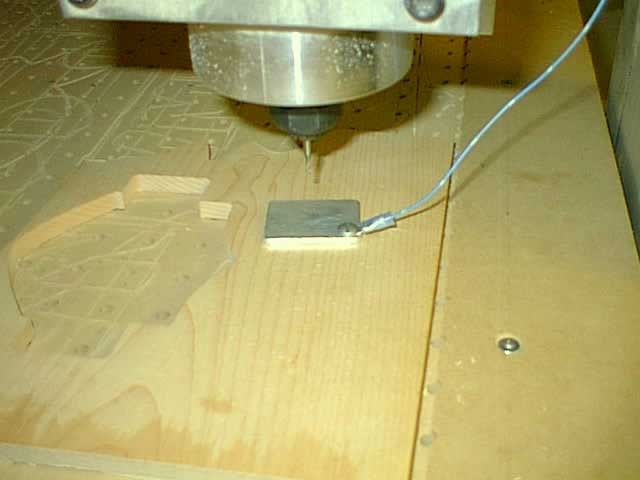
Insulation is not neccesary for a touch plate that sits on wood workpieces!
Here is a switch mounted off to the side that finds a zero for the top of the spoil board (the table) of a router setup:
Touchsetter relatively to table zero on a router--top of spoilboard...

Another homebrew touchsetter switch. This one is pretty tall!

A commerical Blum Nano touchsetter...
If you want to build a probe that works along the principles of commercial devices, Indoor Flyer has an excellent article on one. It's intended for digitizing, but could be used for this purpose as well. Why not make 2 so you have one for each purpose?
If you want to buy a probe, try IMServices. The reviews I've heard on their probes have been great!

How about using an optical limit switch? Industrial Hobbies used to sell these, but now only offer them as part of their CNC kit. I've been working on a design for one. They're pretty simple:

An optical limit switch could be made into a touchsetter switch...
After I determine how accurate my design is in the limit switch application, it wouldn't be hard to re-engineer it for this application where it could be mounted vertically near the home position. The neat thing about the optical limit is the contact closure is completely "soft" as a flag blocks the beam of light to the sensor. As such, over travel is easy to arrange so you can slam into the limit pretty fast, apply minimal back pressure to your cutting tool, and if the axis has a bit of over travel before the switch cuts in, you haven't ruined anything.
Finally, Mariss Freimaniss (Mr Gecko Drive) had an interesting suggestion for those into building probes:
How about a probe rod attached directly (superglued) to a pizeoelectric crystal? Any contact would generate an easy to detect voltage. Take apart a clicker type butane lighter and attach a voltmeter to the wires; it takes the faintest pressure on the crystal to generate a voltage. Nothing moves so the contact/no-contact point hysterisis is negligable.
Another fellow mentioned the availability of small "bimorph" piezoelectric devices to be used as Mariss suggests. He says they put out 4v with 10 micrometers of deflection. That's pretty darned sensitive! Not sure this sensor is ideal for this application, however. It is simple, but the problem is it only sends a brief signal at the point of contact and then stops signalling. It might be necessary to "latch" that signal in some way. Anyway, mechanical switches are cheap and easy.
Setting up Mach 3 for Touchsetting: Basic ScriptOkay, let's take a look at the software component of creating an automatic touchsetter for use with Mach 3 on a mill. First, you need a sensor, which we covered just above. Next, you'll need a macro to position the tool over the sensor and drive down in the Z-axis until contact is made, at which point the Z-position may be used to calculate an appropriate offset. Before going to a lot of trouble to write a custom macro for this purpose, be sure to experiment with the "Set Tool Offset" command on the control panel. This is the manual approach to setting these offsets, and you'll want to be comfortable that your automated approach does something similar without as much manual intervention from you. Basically, you just touch-off the tool, enter any additional offset in the DRO next to the button, and click the button. For example, if you touch down on a gage block, enter the thickness of the block in the additional offset DRO. You want to be very comfortable with all the offsets available in Mach 3 before tackling this job! On the sensor, you need to tell Mach 3 what input pin to use as a probe sensor contact. Use the "Input Pins" dialog to do this. From what I can read in my travels, a Z-axis feed rate on the order of 10"/minute is slow enough to work well without damaging the tool or the sensor. Now about those Mach 3 macros. Here are some samples, use at your own risk until I get my own written (my own comments are after the "//", ignore those!):
Here is another sample macro (written for the router switch shown above) with my "//" comments (as usual, they'd have to be removed before use):
And yet another, even more elaborate macro from the Mach 3 support forum. It is interesting in that it simply keeps track of the difference between the current tool and the newly inserted tool rather than bothering with the tool table. It also shows how to prompt the operator to insert the new tool:
Setting Up Mach 3 for Touchsetting: Interface Niceties... Okay, let's say we have the basic script up and running. How do we access it from within our g-code part program so that we can set the tool length offsets either at the beginning of the program, or in a program that let's you go through your whole rack and set up the table, or for some other application such as after each tool change? One easy approach is to make use of Mach's capacity to create custom M-codes. Let's say you wanted to trigger your macro with an M450. Simply place the following at the top of the macro: SetTriggerMacro (450) would set it to M450 That's pretty cool. We've just added our own canned cycle to Mach to set the tool height! I Wish I Could Say This Is All Done And Easy, But... Despite all the research, I still do not have a definitive macro and touchsetter design that is confirmed working. I have a lot of "almost there" prototypes where an individual got it to work well enough and moved on. It's a pity, but that will give me some challenge working out the bugs when it comes time to built my own | ||||||||||||||||||||||||||||||||||||||||||||||||||||
Sunday, 9 November 2014

Subscribe to:
Post Comments (Atom)
No comments:
Post a Comment